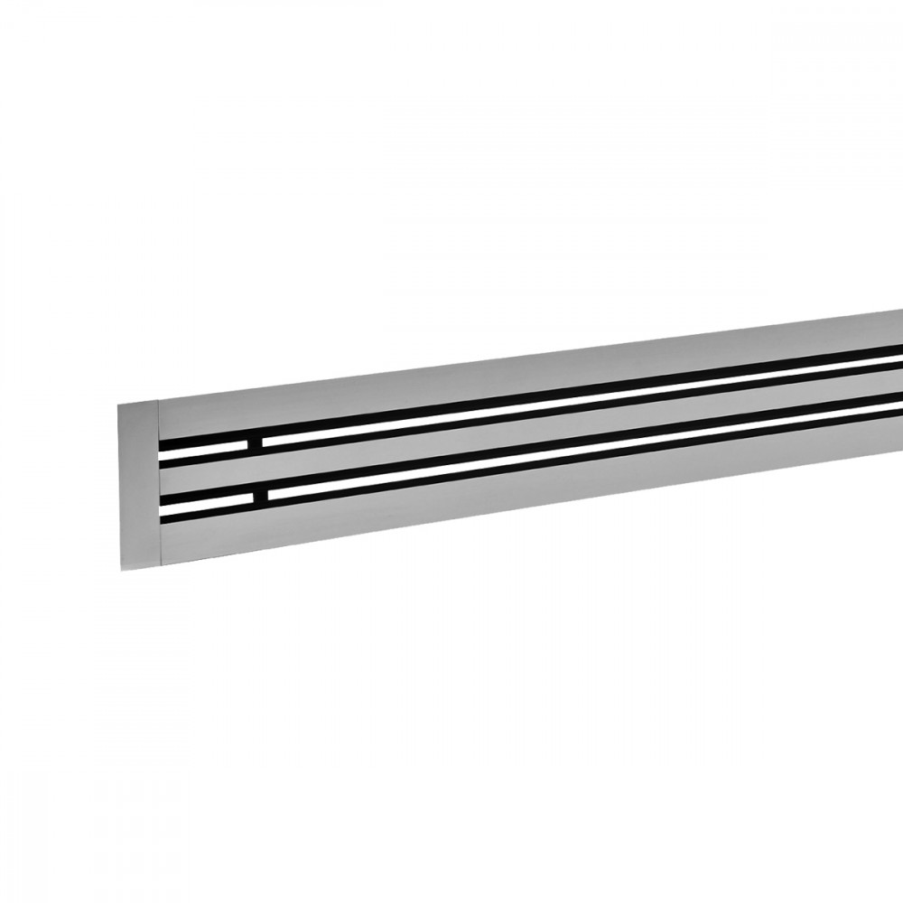
Products

DIFFUSERS

DLF

CHARACTERISTICS:
Linear slot diffusers with black deflectors (standard).
Linear slot diffusers with white deflectors (DLF/DW).
CONSTRUCTION:
Anodized extruded aluminium.
UTILIZATION:
For ceiling installation and for air intake and delivery.
Installation height: 2,5 - 3,1 m.
FIXING:
• By frontal screws.
• By inner mounting mobile bracket.
• By springs inside the plenum.
ACCESSORIES:
• Galvanized steel connecting plenum with insulation.
Dimensions
CHOICE AND SIZING

Mod.

Ak [m2]

Q [m3/h]

LWA [dB(A)]

X(0,25) [m]

Dpt * [Pa]

min

max

min

max

min

max

min

max

DLF1 1000

0,00959

100

230

32

46

3,1

6,9

10

50

DLF2 1000

0,0193

200

460

33

47

4,1

9,2

10

50

DLF3 1000

0,02901

300

690

34

48

4,8

11

10

50

DLF4 1000

0,03872

410

930

35

49

5,6

12,5

10

50

DLF5 1000

0,04843

510

1160

35

49

6,1

13,8

10

50

DLF6 1000

0,05814

610

1390

36

50

6,6

14,8

10

50

DLF7 1000

0,06785

710

1620

36

50

7

15,8

10

50

DLF8 1000

0,07757

820

1860

37

51

7,5

16,9

10

50

* without equalizer and calibration damper completely open

Accessories and configurations

PDL1

1= Tube

2= spring

Fixing to the plenum by springs CM


PDL2

1= Fixing screws

2= Inner mounting bracket

Fixing to the plenum by inner mounting brackets CVL


PDL3

1= Fixing screws

2= Inner mounting bracket inclinated

Fixing to the plenum by inner mounting brackets inclinated CVL


DLF10

DLF40

DLF20

DLF50

DLF30

DLF

N.= slots

L mm= Lenght

Ø= spigots

N.= spitos

CVL = Mounting brackets

CM= Spring


Instructions

CONTINUITY SOLUTION

Clamping point

Insert the bracket into the profile in the direction indicated.


CONTINUITY SOLUTION

Insert the bracket to penetrate up to 10/15 mm the clamping point.


CONTINUITY SOLUTION

Combine the 2 parts.


CONTINUITY SOLUTION

Connection point


CVL

Configuration change CVL to PDL 3 to PDL 2 with finger pressure


DLF DIFFUSER PLENUM PDL1 ASSEMBLY DIAGRAM

1) Hook the spring to the mounting tube placed inside the plenum.


DLF DIFFUSER PLENUM PDL1 ASSEMBLY DIAGRAM

2) Move the deflectors with a screwdriver so as to leave most free surface by the action of the hook.


DLF DIFFUSER PLENUM PDL1 ASSEMBLY DIAGRAM

3) Bringing the diffuser to the plenum, by means of the hook to extend the spring and hook it to the self-locking pin on the diffuser so block the way unitary structure.

1= pull-out stop loop

2= tube in the plenum

3= self-locking pin on the diffuseR


DLF DIFFUSER PLENUM PDL1 ASSEMBLY DIAGRAM

4) Ensure sure that the attachment is safe.

1= pull-out stop loop

2= tube in the plenum

3= self-locking pin on the diffuser

 
Specifications text

ALUMINIUM LINEAR SLOT DIFFUSER WITH ALUMINUM DEFLECTORS

CONSTRUCTION:
Extruded anodised aluminium.
Black Deflectors (Standard) - White Deflectors (DLFDW on request)
USE:
On the ceiling, for air supply and return. Installation height:2.5 - 3.1 m
INSTALLATION:
• By front screws.
• With movable internal bracket.
• With springs inside the plenum.
ACCESSORIES:
• Connection plenum in galvanised steel with insulation.
MODEL:DLF**/***/*** (type-number of slots-length mm)


Documents download
Information request

Write us a message

Brofer Srl - All rights reserved - P.I. 01459590285

Cap. soc. i.v. € 100.000 Reg. imp. PD R.E.A. n° PD - 161099

Questo sito utilizza cookie tecnici e funzionali per migliorare la tua esperienza di navigazione. Con il tuo consenso vorremmo attivare cookie con finalità di analisi e di marketing, allo scopo di migliorare la tua esperienza di navigazione e di mostrarti prodotti e servizi di tuo interesse. Puoi modificare le tue impostazioni in qualsiasi momento nella pagina delle condizioni sui cookie. Nella stessa pagina troverai informazioni sul responsabile della gestione dei tuoi dati, il trattamento dei dati personali e le finalità di tale trattamento.
Select your preferences on cookies.
Cookie tecnici
Cookie statistiche + marketing
Approva tutti