

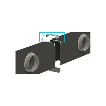
PDLCC
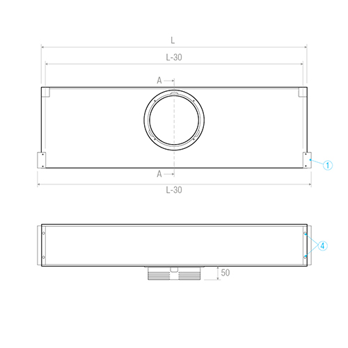
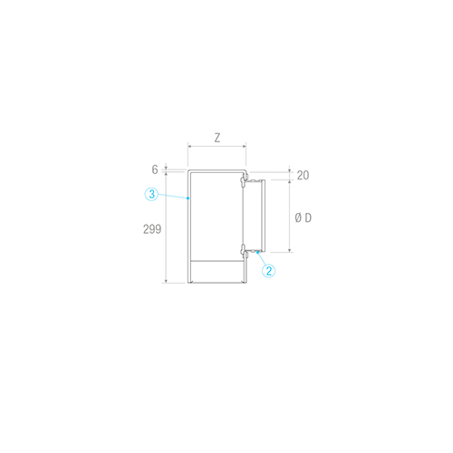
A= Internal share
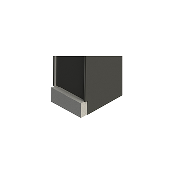
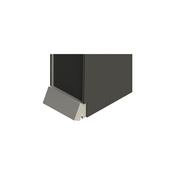
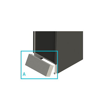
1= Side cap to be removed in case of continuity
4= Holes Ø 9 for mounting
PDLCC
Section A-A
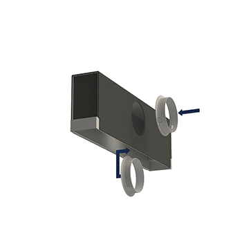
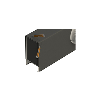
2= Plastic spigot supplied with customized mounting
3= Polyethylene outer insulation thickness 6 mm
PHASE 1:
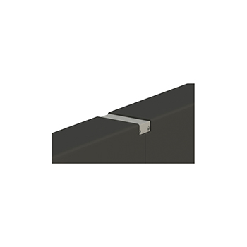
Force the head part on the side that will form the line of continuity along the pre-cut line (Fig. 1) until the bottom of the head is released (Fig. 2 / Fig. 3). Store the part of the header named A. Installation of the spigot on the plenum (fig. 4). Cut with cutter and remove the end of the insulation so that you can install A (fig.5).
PHASE 2:
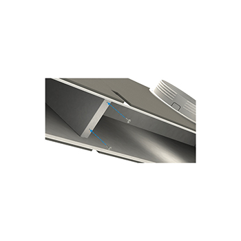
Go near the two plenums by ensuring the flatness and the precise coincidence between the pieces (Fig. 6). Install the top part of the junction of the two plenums with the previously removed A part and secure it with self-tapping screws supplied with the Kit (fig.6 / fig.7). Fix the plenum boxes internally with the screws supplied with the kit (fig.8).
PHASE 1:
Force the head part on the side that will form the line of continuity along the pre-cut line (Fig. 1) until the bottom of the head is released (Fig. 2 / Fig. 3). Store the part of the header named A. Installation of the spigot on the plenum (fig. 4). Cut with cutter and remove the end of the insulation so that you can install A (fig.5).
PHASE 2:
Go near the two plenums by ensuring the flatness and the precise coincidence between the pieces (Fig. 6). Install the top part of the junction of the two plenums with the previously removed A part and secure it with self-tapping screws supplied with the Kit (fig.6 / fig.7). Fix the plenum boxes internally with the screws supplied with the kit (fig.8).
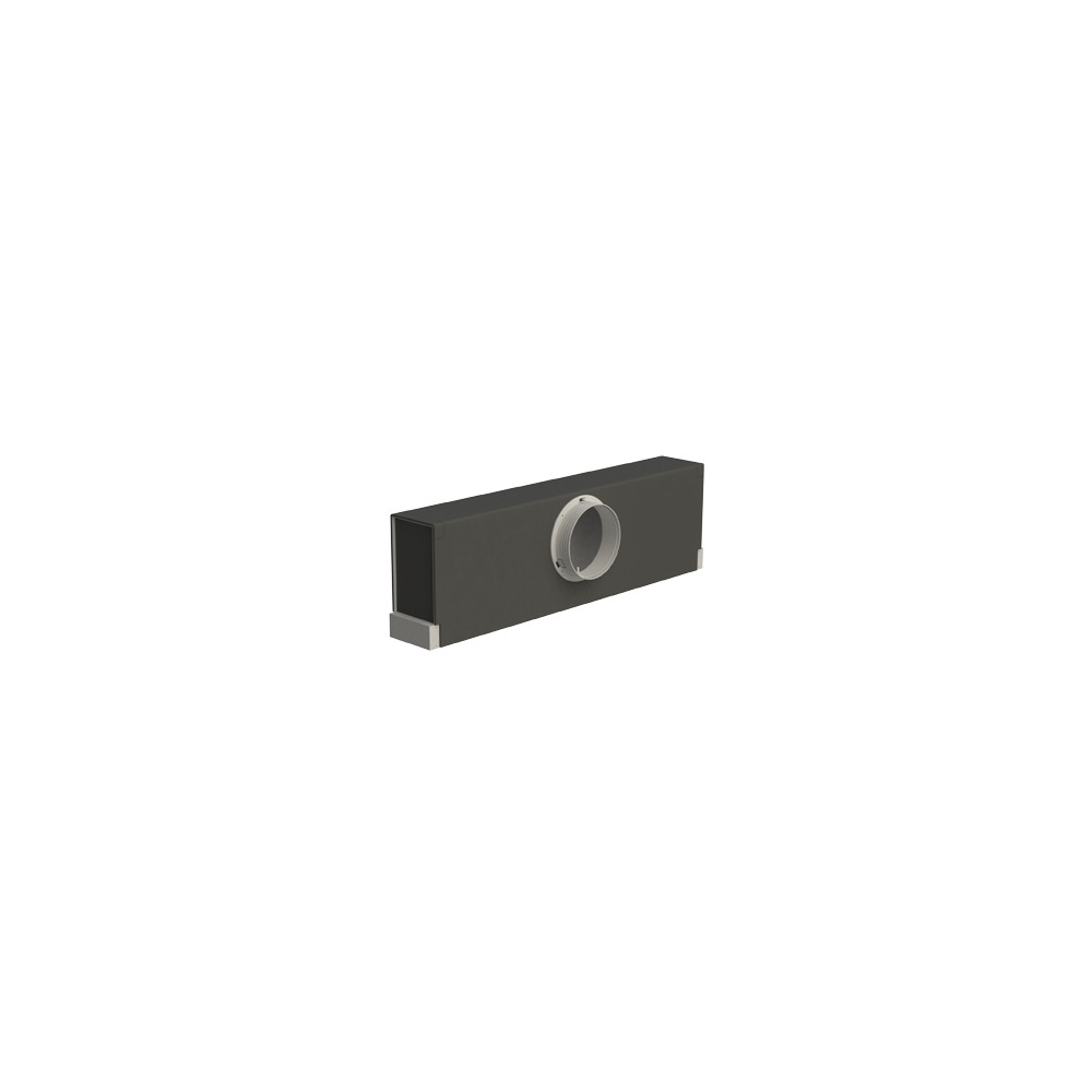
MULTIFUNCTION PLENUM IN GALVANISED STEEL INSULATED EXTERNALLY WITH PLASTIC MATERIAL ATTACHMENTS FOR LINEAR DIFFUSERS MODEL DLF/DLN.
CONSTRUCTION:
Made of galvanised steel (PDLCC model) with external insulation in polyethylene th.6 mm (PDLCCI model) and outputs in plastic.
USE:
Suitable at the same time for installation with a single diffuser and for the creation of continuous lines.
INSTALLATION:
Assembly of the diffuser to the plenum by means of inclined brackets (CVL) and screws, all included in the kit.
PACKING:
Single Kit packed with protective nylon.
MODEL: PDLCC/***/*** (no. slots-length mm)
Brofer Srl - All rights reserved - P.I. 01459590285
Cap. soc. i.v. € 100.000 Reg. imp. PD R.E.A. n° PD - 161099
 PDLCCI
 Write us a message


